Section 3 / stress analysis toolkit

Over 100 tools for recurring aerospace engineering problems.

The suite is organized around the checks engineers repeat daily. Each tool should turn inputs, assumptions, and theory into a clear engineering result.

Panels and stiffened shells

Compression, shear, bending, pressure, combined loading, local instability, and stiffener interaction.

D = Et^3 / 12(1 - ν^2)

Joints, fasteners, and fittings

Bearing, bypass, tear-out, net-section, lug, pin, bolted-joint, and fitting load transfer checks.

σbr = P / td

Beams, frames, and columns

Section properties, shear flow, bending stress, torsion, column buckling, crippling, and interaction ratios.

P / Pcr + M / Mallow ≤ 1

Pressure and membrane structures

Hoop stress, meridional stress, fabric loads, pressure-vessel checks, and envelope attachment load paths.

σθ = pr / t

Buckling and stability

Eigenvalue buckling, knockdown factors, shell sensitivity, panel crippling, and slender member stability.

(K + λKG)φ = 0

Thermal and material effects

Thermal strain, material knockdowns, stiffness changes, elastic allowables, and design sensitivity studies.

εth = αΔT

Composite and laminate checks

Orthotropic stiffness, transformed plies, laminate resultants, failure indices, and directional margins.

N = Aε0 + Bκ

Loads and margins

Limit and ultimate loads, reserve factors, margin of safety reports, and consistent calculation templates.

RF = allowable / applied

Engineering documentation

Reusable assumptions, equations, units, references, load cases, and audit-ready calculation summaries.

MS = RF - 1
01

CFRP Laminate structure MRB analysis and reporting on manufacturing or in-service defects.
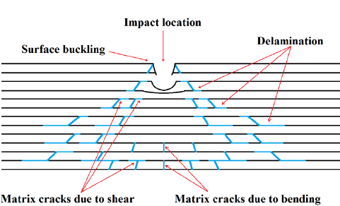
CFRP laminate impact damage diagram showing impact location, surface buckling, delamination, matrix cracks due to shear, and matrix cracks due to bending.
Passcode required
02

Loading parametric study creating Potato plots of stress, strain, loading and deformation.
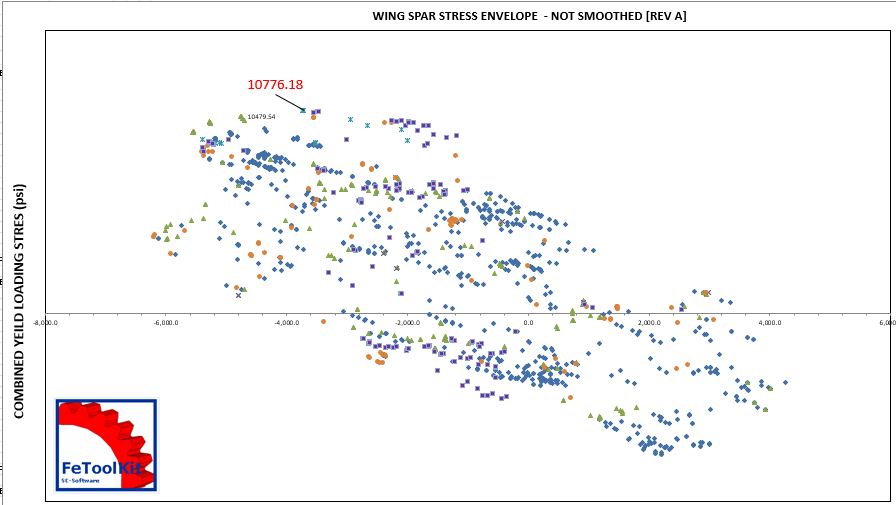
Wing spar stress envelope plot showing a FeToolKit potato plot of combined yield loading stress with scatter points and FeToolKit logo.
Passcode required
03

NASA checks on bolted joint integrity to 'NASA-STD-5020A'.
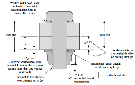
Bolted joint integrity diagram showing washer, joint grip, bolt grip, thread pitch, lead threads, and required clearances for NASA-STD-5020 style checks.
Passcode required
04

Buckling, Crippling, Fatigue and Damage Tolerance Analysis.
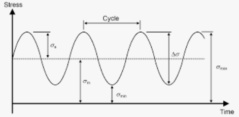
Fatigue stress cycle diagram showing cyclic stress variation with mean stress, maximum stress, minimum stress, amplitude, and stress range over time.
Passcode required
05

Stress Concentration Analysis.

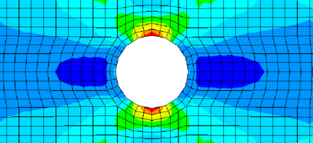
Finite element stress concentration contour plot around a circular hole showing local high stress bands around the cut-out and lower stress fields away from the hole.
Passcode required
06

Tension Fitting and Lug Analysis.

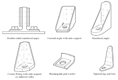
Tension fitting and lug analysis diagram showing double-sided machined angle, formed angle with side support, machined angle, corner fitting, rectangular pad washer, and tapered leg and foot examples.
Passcode required
07

EJMA bellows convolution stress and parametric fatigue analysis.
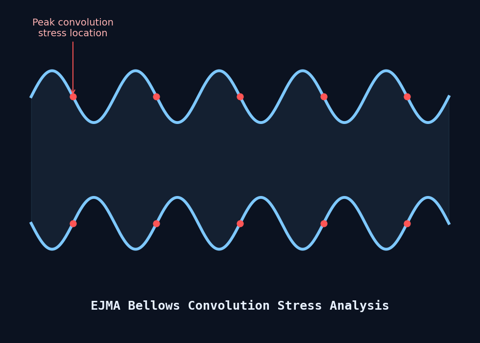
EJMA bellows convolution stress diagram showing a corrugated bellows profile with peak stress locations marked at each convolution root.
Passcode required
08

Unified Thread Standard (UN/UNF/UNEF) dimension lookup, Class 2A/2B.
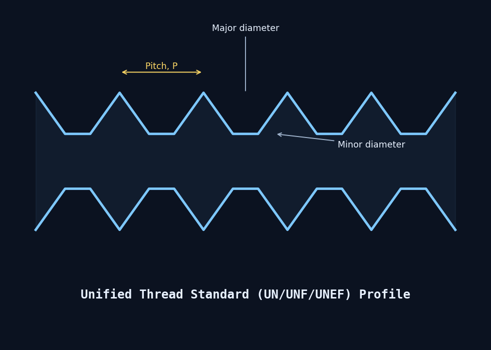
Unified Thread Standard profile diagram showing major diameter, minor diameter, and thread pitch for UN/UNF/UNEF threads.
Passcode required
09

Aircraft fuselage hoop and longitudinal skin stress, window cutout concentration, and frame-bay deflection.
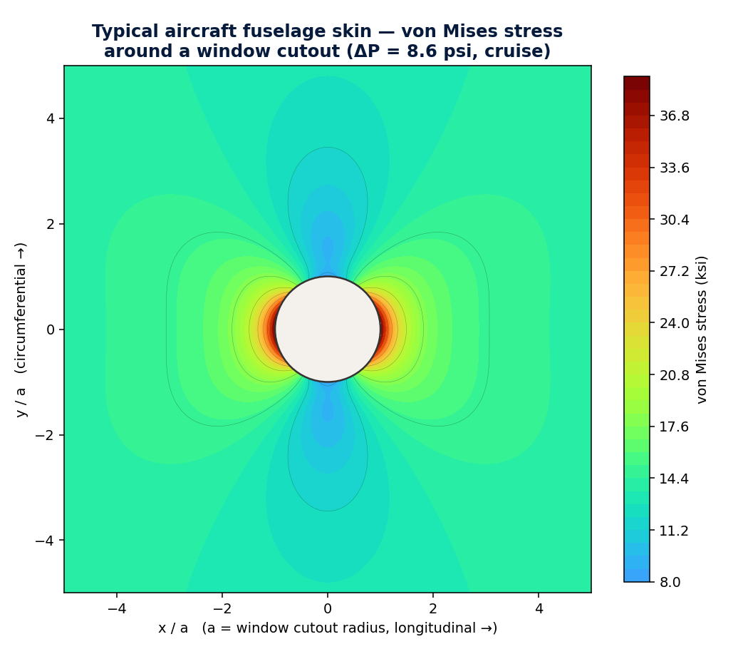
Von Mises stress contour around a fuselage window cutout, showing local stress concentration.
Passcode required
10

Flight comfort and gust response — discrete-gust incremental load factor (Pratt formula, FAR/CS-25 §25.341).

Wing spar stress envelope plot showing combined gust and maneuver loading.
Passcode required

Subsection 3.1 / FeToolKit program screens

See the software environment, menus, and specialist engineering modules.

Below are representative FeToolKit program screens showing the interface used for finite element import, stress analysis workflows, composite repair utilities, fastener calculations, and results-led engineering assessment. This subsection helps visitors understand that FeToolKit is not only a theory-driven toolkit, but also a practical production environment for day-to-day aerospace structural work.

What this subsection demonstrates

FeToolKit combines a long heritage of aerospace stress analysis with a task-focused software interface. The screenshots illustrate both the broad menu-driven toolkit and dedicated problem pages built for common engineering checks.
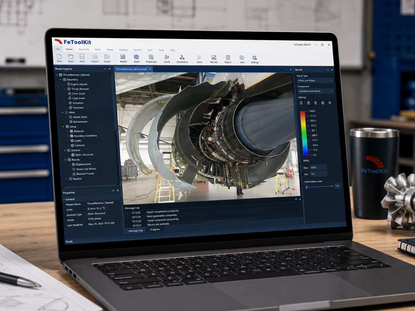
  • 1Integrated workflow: geometry, mesh, loads, constraints, solver setup, results review, and reporting are organized into an efficient engineering process.
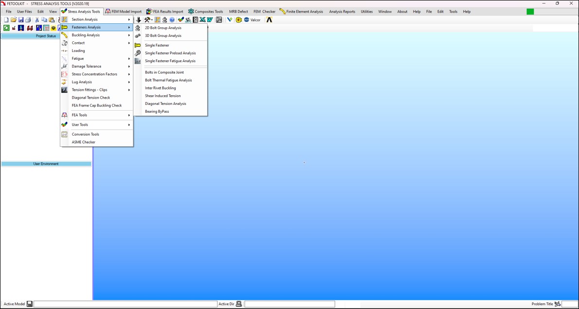
  • 2Specialist tools: menus expose targeted modules for composites, defect assessment, panel checks, fasteners, joints, finite element utilities, and technical reporting.
  • 3Calculation depth: dedicated pages support practical data entry, design factors, loading variables, allowable strength checks, and engineering margins.
  • 4Aerospace relevance: the emphasis remains on the recurring structural problems aerospace engineers solve every working day.
FeToolKit software shown on a laptop with a modern engineering workspace, displaying a structural analysis model and results interface.
Modern workspace view. A contemporary FeToolKit environment presenting model navigation, setup controls, solution management, and results visualization within a single engineering workspace.
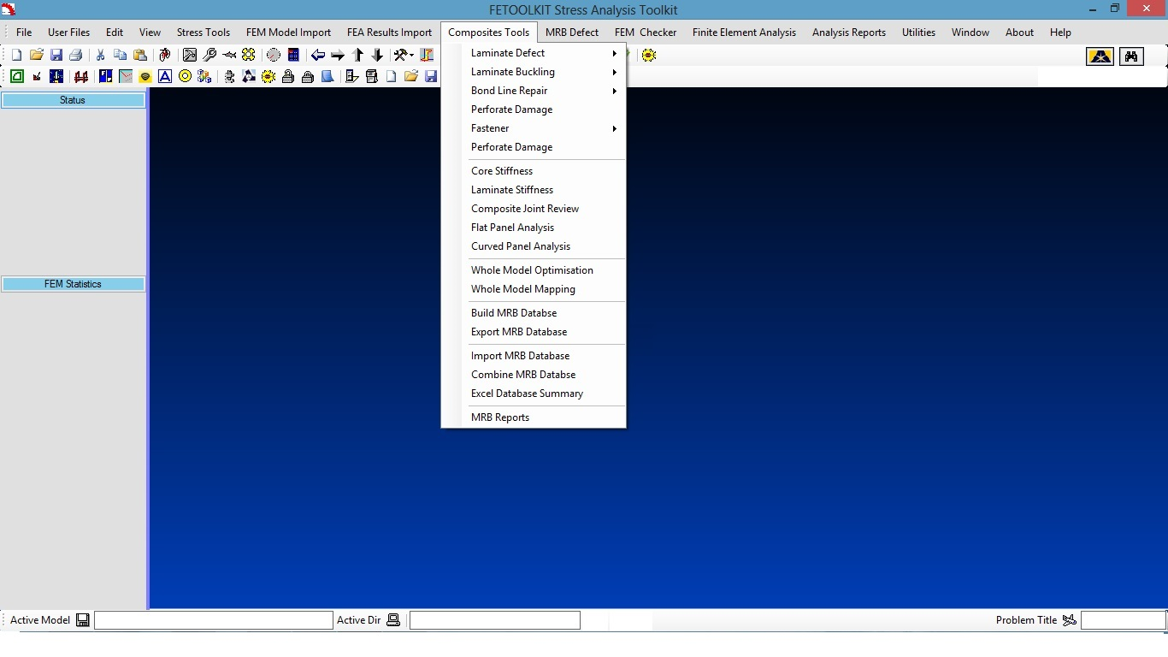
FeToolKit Stress Analysis Toolkit screen with the Composites Tools menu open, showing laminate defect, buckling, bond line repair, perforate damage, fastener, panel analysis, and MRB options.
Composite tools menu. This screen shows the breadth of composite-focused capability, including laminate defect assessment, buckling, perforate damage, fastener options, flat and curved panel analysis, and MRB database/report functions.
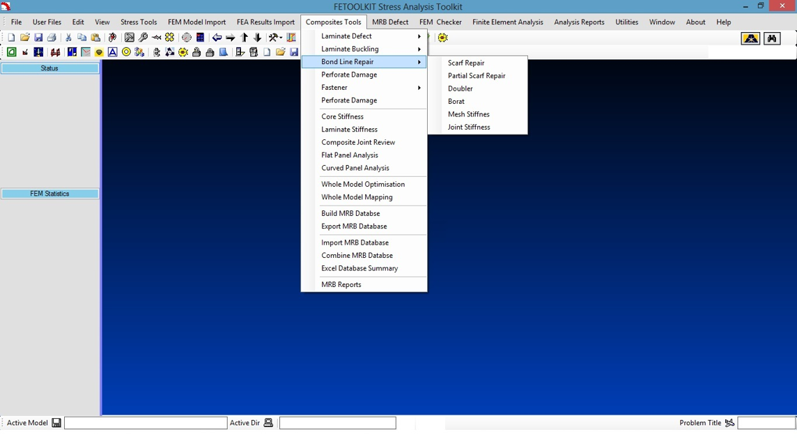
FeToolKit screen showing the Bond Line Repair submenu under Composites Tools, with scarf repair, partial scarf repair, doubler, borat, mesh stiffness, and joint stiffness options.
Bond line repair utilities. A dedicated submenu for scarf repair, partial scarf repair, doublers, borat-style checks, mesh stiffness, and joint stiffness — reflecting the practical repair-analysis orientation of the suite.
FeToolKit menu showing Stress Analysis Tools with options such as section analysis, fasteners analysis, buckling analysis, contact, loading, fatigue, damage tolerance, lugs, tension fittings and clips, and other user tools.
Stress analysis tool access. The classic menu-driven structure exposes section analysis, fastener analysis, buckling, fatigue, damage tolerance, lugs, fittings, and additional engineering/user tools for rapid technical problem solving.
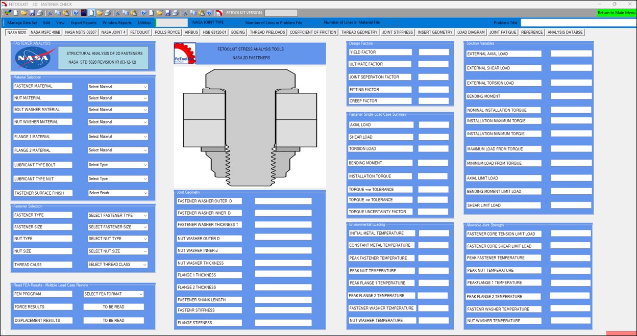
FeToolKit 2D Fastener Check page showing a NASA-based fastener analysis form with material selection, geometry, design factors, loading variables, and allowable joint strength sections.
Detailed fastener module. This application page shows a structured calculation workflow for a 2D fastener check, including material selection, geometry, load inputs, design factors, and allowable joint strength evaluation.